Two PSUs, one power button – a DIY ATX relay switching module
A compact DIY relay module built on perfboard to coordinate the power-on signal of a secondary ATX PSU. A closer look at the prototype, ATX PS_ON# control and essential electrical safety considerations.
When one power supply is no longer enough
Some computer builds and workshop projects call for a second power supply. Beyond selecting sufficient power capacity, there is another question: how can the auxiliary PSU turn on and off with the main system? A small relay-based controller can help coordinate this switching function.
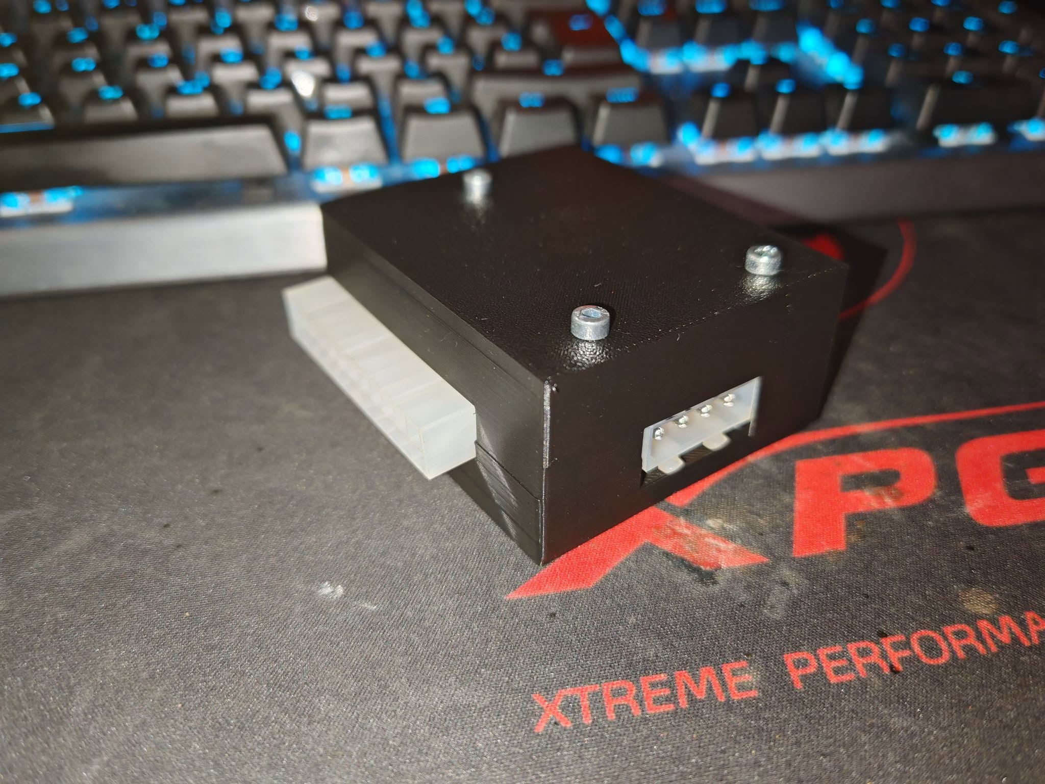
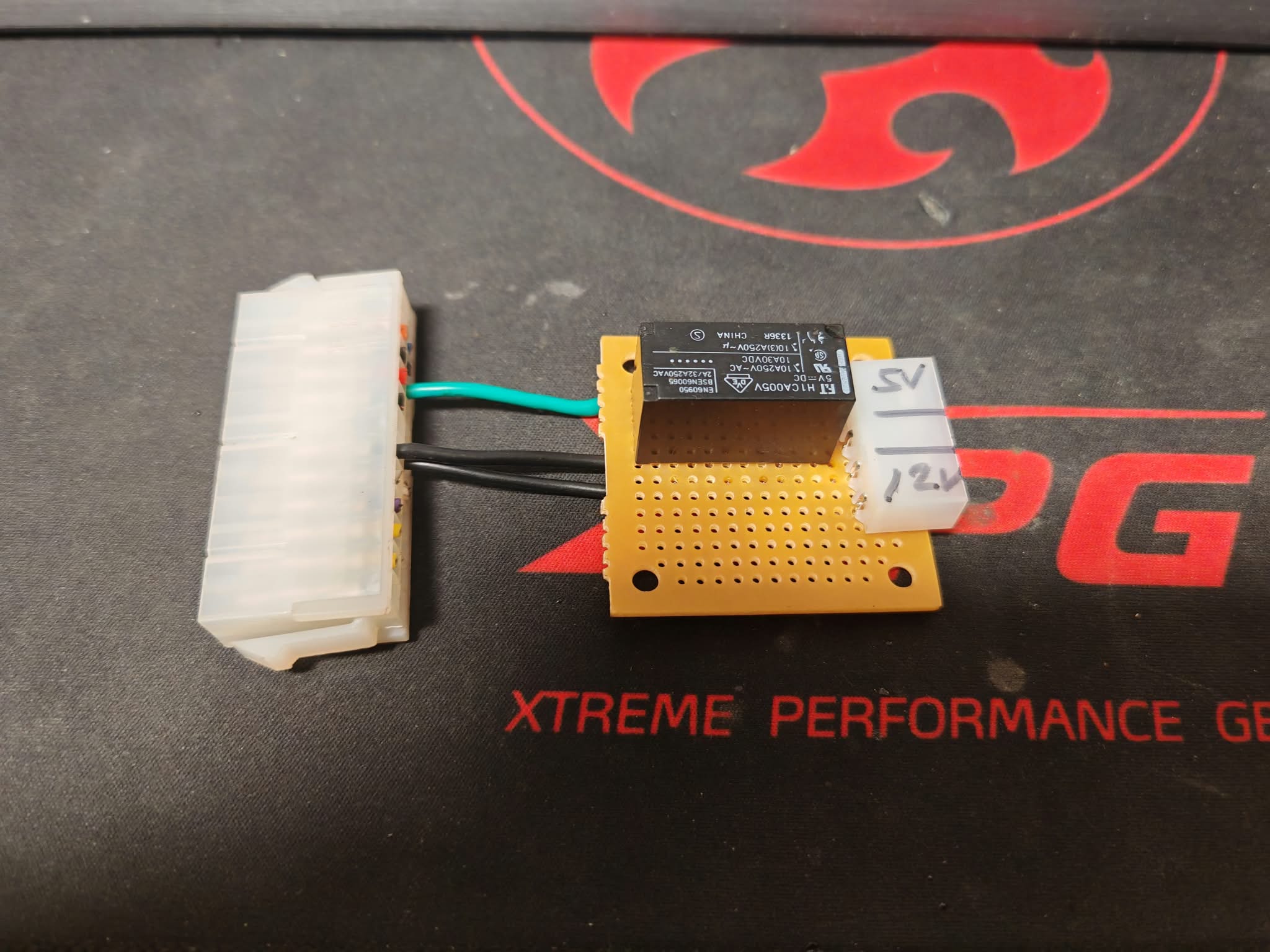
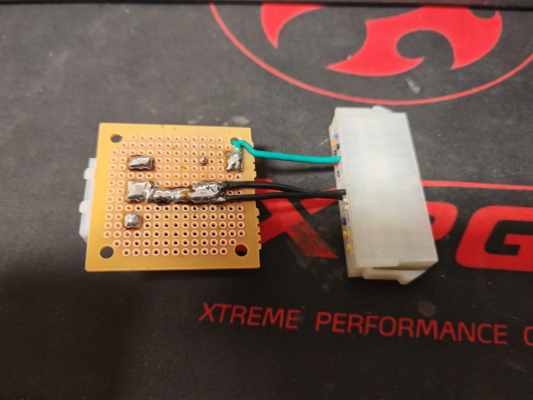
The photographs show a home-built secondary PSU switching module assembled on perfboard. This is a workshop prototype, not a certified commercial product. Its visible parts include a relay, an ATX-style multi-pin connector, several wires and a hand-labelled terminal.
What is visible in the photographs?
- Relay: the marking identifies it as an FT H1CA005V with a 5 V DC coil. The printed contact ratings include 10 A at 250 V AC and 10 A at 30 V DC. These are ratings shown on the relay itself, not a verified rating of the complete hand-built assembly.
- ATX-style connector: a large white multi-pin connector with one green wire and multiple black wires can be seen.
- Labelled terminal: the smaller white connector carries handwritten “5V” and “12V” labels. The exact functions of its terminals cannot be confirmed from the labels alone.
- Perfboard construction: the relay and wiring are mounted to a solderable prototyping board.
How can a relay coordinate two ATX power supplies?
An ATX PSU normally has an active-low PS_ON# control input. Pulling this input to the appropriate COM/GND reference requests that the supply turn on. In common ATX wiring conventions, PS_ON# is green and COM wires are black. The actual connector pinout must always be checked against the specific power supply documentation.
In one common design, an operating output from the primary PSU energizes a relay coil. A correctly chosen normally-open (NO) relay contact then connects PS_ON# to COM on the secondary PSU. Once the main supply switches off, the relay releases and removes the secondary power-on request. This describes a general ATX switching method, not a verified schematic of the photographed prototype.
The two supplies can therefore be started together without directly paralleling their +12 V outputs. Load distribution and reference-ground arrangements still need to be designed for the actual system.
Technical and safety considerations
- +5 V versus +5VSB: the ATX standby rail may remain powered while the PC appears switched off. The relay trigger must be taken from a signal that reflects the intended operating state.
- Switch the control signal, not load current: PS_ON# is a low-current input. Do not route high-current GPU, motor or other equipment power through these relay contacts.
- Coil transient protection: a DC relay coil needs appropriate inductive kickback protection for its driver. The photos do not establish whether such protection is fitted.
- Verify before energizing: use a multimeter to identify coil pins, contact terminals and default contact state, and to check solder bridges and possible shorts.
- Electrical safety: ATX PSUs operate from mains voltage. Do not open the PSU enclosure for this project. Use properly designed low-voltage external connectors only, and do not run an unverified prototype unattended.
Where could the design go next?
Perfboard is useful for proving an idea, but a durable system-ready version would benefit from a dedicated PCB, labelled and mechanically secured connectors, strain relief, appropriate circuit protection and an enclosed housing. A 3D-printed enclosure may be an option if its material and design meet the actual thermal and fire-safety requirements.
In summary: coordinating a secondary ATX PSU can be achieved with relatively few components. The photographed assembly is an interesting starting point for a fully documented version, but photographs cannot replace a verified schematic or electrical testing.