3DPS logo
3DPS Europe
Service and development
News

News / article

Curiosities & Astonishing Stories
← Back to news Back to homepage
Two PSUs, one power button – a DIY ATX relay switching module
2026. 10. 31.
335

Two PSUs, one power button – a DIY ATX relay switching module

4 min read

A compact DIY relay module built on perfboard to coordinate the power-on signal of a secondary ATX PSU. A closer look at the prototype, ATX PS_ON# control and essential electrical safety considerations.

When one power supply is no longer enough

Some computer builds and workshop projects call for a second power supply. Beyond selecting sufficient power capacity, there is another question: how can the auxiliary PSU turn on and off with the main system? A small relay-based controller can help coordinate this switching function.

The photographs show a home-built secondary PSU switching module assembled on perfboard. This is a workshop prototype, not a certified commercial product. Its visible parts include a relay, an ATX-style multi-pin connector, several wires and a hand-labelled terminal.
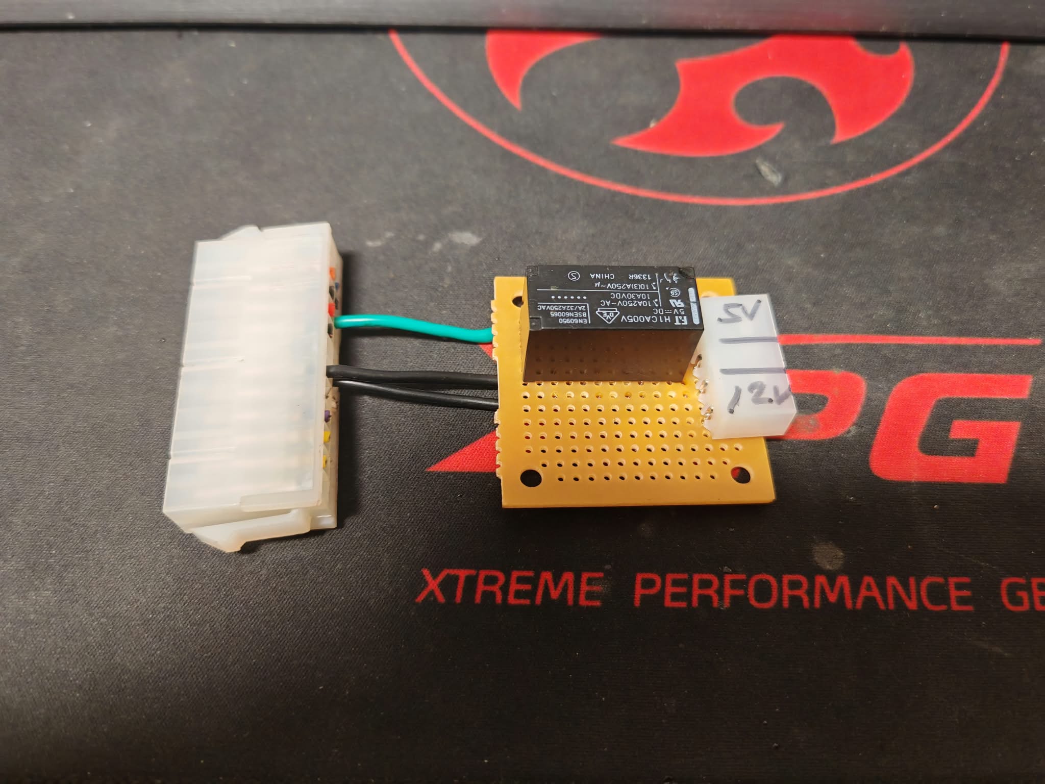
Top side of a DIY secondary ATX PSU switch with relay, perfboard and connectors
Component side of the home-built module, showing the relay, perfboard, an ATX-style connector and a hand-labelled terminal.

What is visible in the photographs?

  • Relay: the marking identifies it as an FT H1CA005V with a 5 V DC coil. The printed contact ratings include 10 A at 250 V AC and 10 A at 30 V DC. These are ratings shown on the relay itself, not a verified rating of the complete hand-built assembly.
  • ATX-style connector: a large white multi-pin connector with one green wire and multiple black wires can be seen.
  • Labelled terminal: the smaller white connector carries handwritten “5V” and “12V” labels. The exact functions of its terminals cannot be confirmed from the labels alone.
  • Perfboard construction: the relay and wiring are mounted to a solderable prototyping board.

How can a relay coordinate two ATX power supplies?

An ATX PSU normally has an active-low PS_ON# control input. Pulling this input to the appropriate COM/GND reference requests that the supply turn on. In common ATX wiring conventions, PS_ON# is green and COM wires are black. The actual connector pinout must always be checked against the specific power supply documentation.

In one common design, an operating output from the primary PSU energizes a relay coil. A correctly chosen normally-open (NO) relay contact then connects PS_ON# to COM on the secondary PSU. Once the main supply switches off, the relay releases and removes the secondary power-on request. This describes a general ATX switching method, not a verified schematic of the photographed prototype.

The two supplies can therefore be started together without directly paralleling their +12 V outputs. Load distribution and reference-ground arrangements still need to be designed for the actual system.
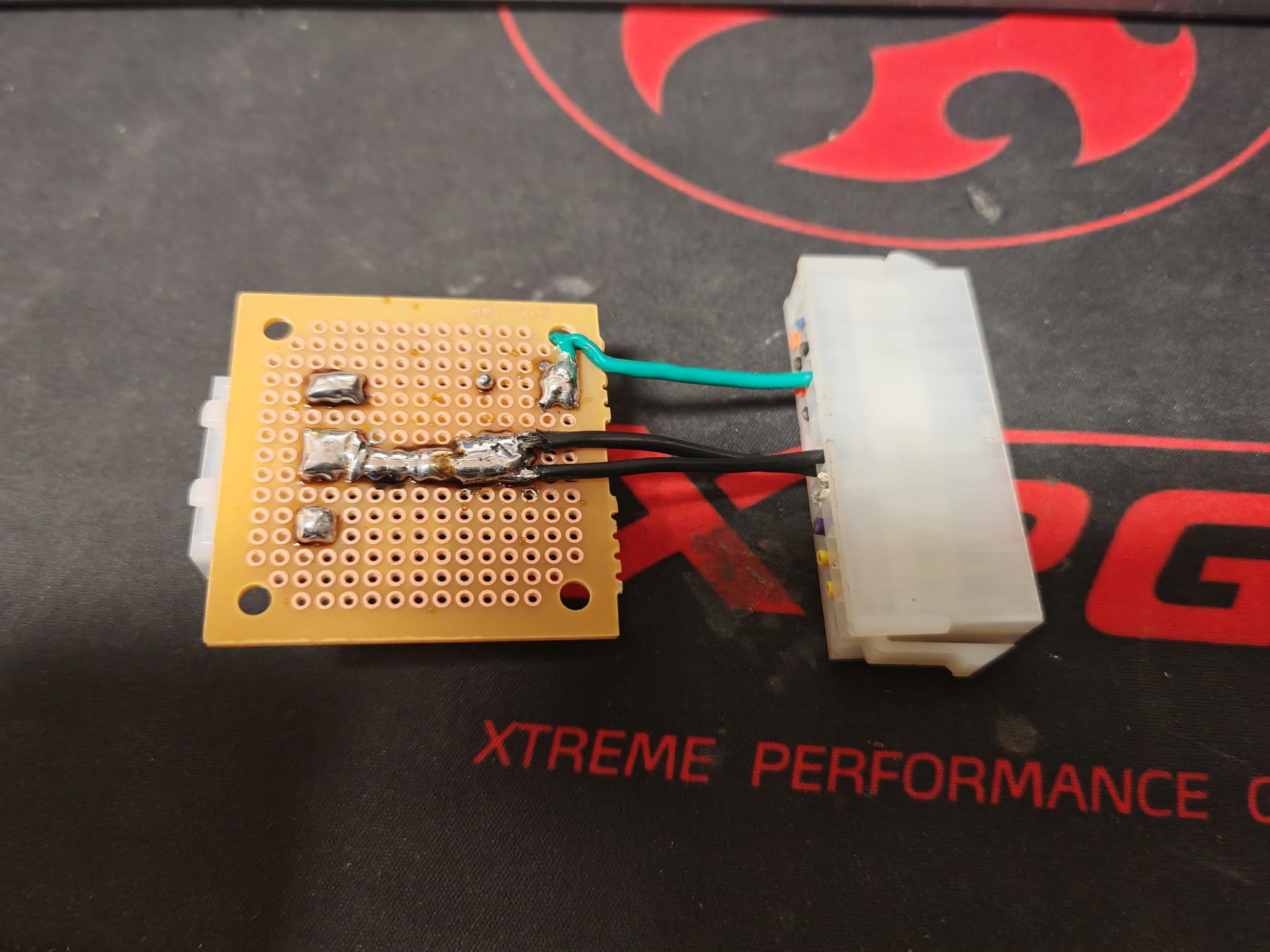
Solder side of the DIY secondary power-supply switching module
Solder side with the wire joints and connections. The complete electrical circuit cannot be verified from a photograph alone.

Technical and safety considerations

  • +5 V versus +5VSB: the ATX standby rail may remain powered while the PC appears switched off. The relay trigger must be taken from a signal that reflects the intended operating state.
  • Switch the control signal, not load current: PS_ON# is a low-current input. Do not route high-current GPU, motor or other equipment power through these relay contacts.
  • Coil transient protection: a DC relay coil needs appropriate inductive kickback protection for its driver. The photos do not establish whether such protection is fitted.
  • Verify before energizing: use a multimeter to identify coil pins, contact terminals and default contact state, and to check solder bridges and possible shorts.
  • Electrical safety: ATX PSUs operate from mains voltage. Do not open the PSU enclosure for this project. Use properly designed low-voltage external connectors only, and do not run an unverified prototype unattended.

Where could the design go next?

Perfboard is useful for proving an idea, but a durable system-ready version would benefit from a dedicated PCB, labelled and mechanically secured connectors, strain relief, appropriate circuit protection and an enclosed housing. A 3D-printed enclosure may be an option if its material and design meet the actual thermal and fire-safety requirements.

In summary: coordinating a secondary ATX PSU can be achieved with relatively few components. The photographed assembly is an interesting starting point for a fully documented version, but photographs cannot replace a verified schematic or electrical testing.

Related articles
Trump T1: Made in America?! When the American Dream Arrives as a Gold-Painted HTC
2026. 10. 29.
795

Trump T1: Made in America?! When the American Dream Arrives as a Gold-Painted HTC

American manufacturing. American values. American pride. That was the story behind the Trump Mobile T1 smartphone. But when iFixit examined the device, the gold-colored exterior revealed something surprisingly familiar: hardware virtually identical to the HTC U24 Pro released in 2024. So what exactly are customers buying — American engineering or a carefully packaged political marketing message?

Archive

Earlier news

96 earlier article(s)
KPI features have been added.
Technology
1 353

KPI features have been added.

KPI features have been added. CALIBRA – Measurem Why do KPIs matter in measurement equipment management? Because data becomes truly useful only when it helps you see where attention is needed and how performance changes over time.

2026. 08. 24.
Read
CALIBRA – A Free Measurement Equipment Management System Is Under Development
Technology
1 198

CALIBRA – A Free Measurement Equipment Management System Is Under Development

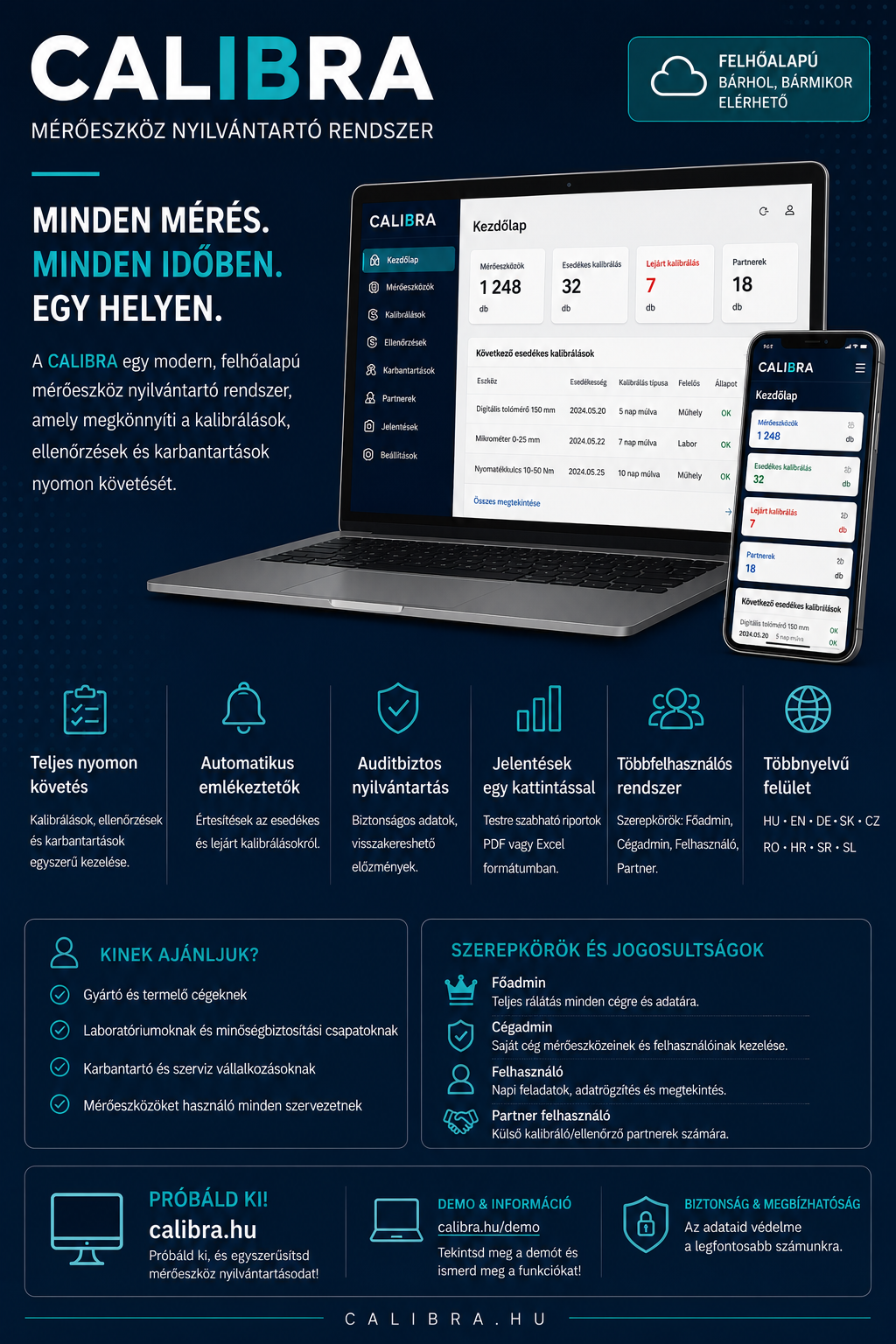
CALIBRA – A Free Measurement Equipment Management System Is Under Development A new in-house developed web application is joining the growing collection of 3DPS projects. CALIBRA is being developed as a modern, transparent and expandable measurement equipment and calibration management system. Development has progressed rapidly from the original concept to an already functioning web application, with the foundations of company management, equipment tracking, external partner management and auditing now in place.

2026. 08. 11.
Read
Parkside Multi Charger: Controller Architecture for the Basic and Pro Versions
Technology
1 257

Parkside Multi Charger: Controller Architecture for the Basic and Pro Versions

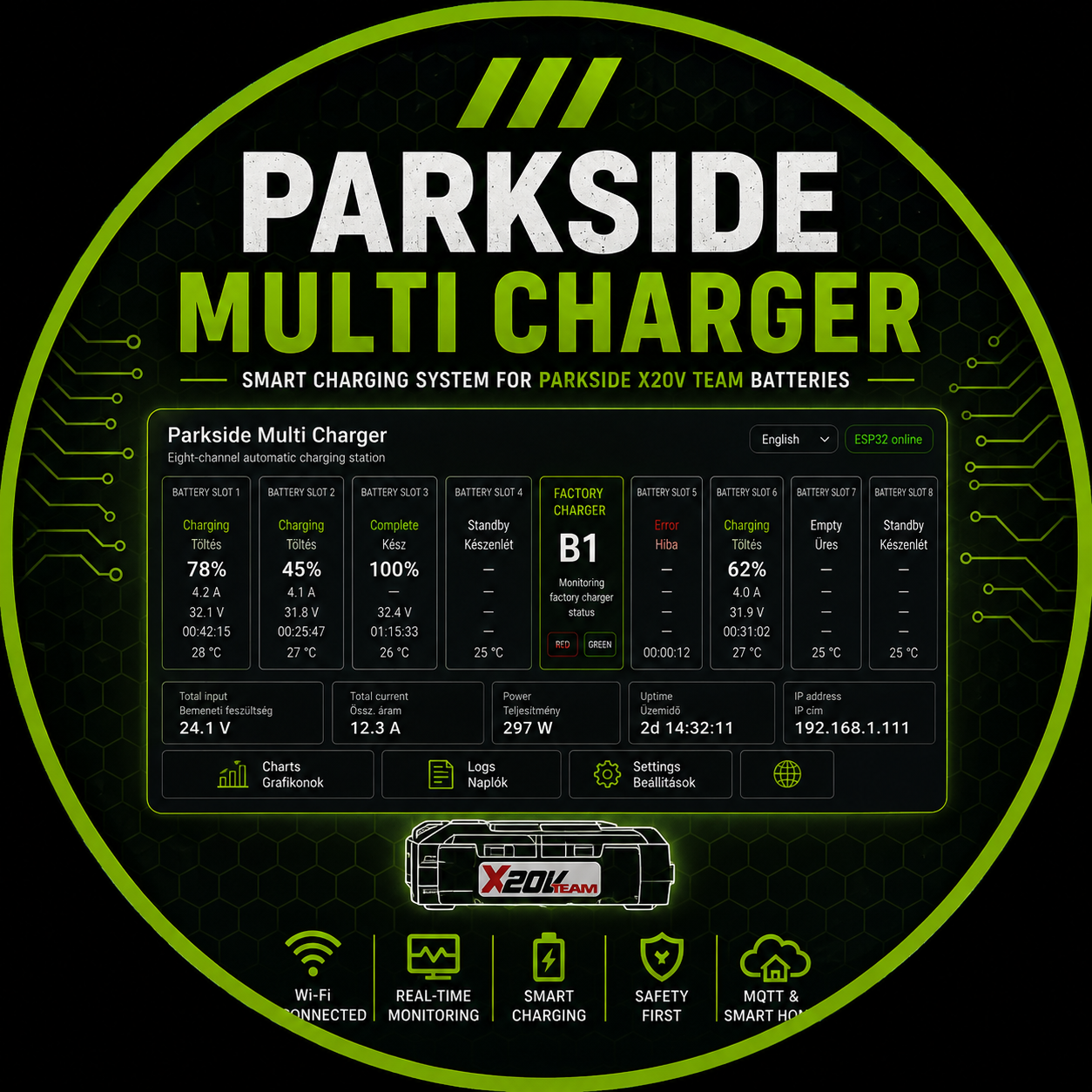
Parkside Multi Charger: Controller Architecture for the Basic and Pro Versions Development of the Parkside Multi Charger has entered a new stage. During the latest planning phase, several controller and power-switching architectures were compared to find a solution that keeps the Basic version easy to build while leaving enough room for the more advanced Pro model.

2026. 08. 04.
Read
Parkside Multi Charger – New Development Milestone
Technology
1 019

Parkside Multi Charger – New Development Milestone

Parkside Multi Charger – New Development Milestone Development of the Parkside Multi Charger continues to make steady progress. Recent work has focused not only on hardware and software development but also on establishing the project's public identity and communication. The project currently consists of two separate development branches: Parkside Multi Charger (Normal) and Parkside Multi Charger Pro.

2026. 08. 02.
Read
Anycubic Kobra 3 toolhead – successful firmware backup and the first steps toward a CAN-based Klipper toolboard
New printers
909

Anycubic Kobra 3 toolhead – successful firmware backup and the first steps toward a CAN-based Klipper toolboard

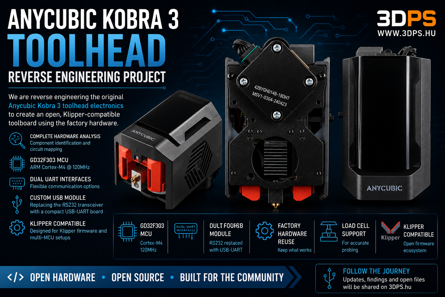
Anycubic Kobra 3 Toolhead Project – Another Milestone: Successful Firmware Backup and Preparing for a CAN-Based Toolboard Today marked another major milestone in the Anycubic Kobra 3 Toolhead project. Our objective is not to modify or preserve the original firmware. Instead, we are developing a completely custom firmware that will transform the factory controller board into a Klipper-compatible CAN Tool MCU with only minimal hardware modifications.

2026. 07. 27.
Read
Another Milestone Reached in the Anycubic Kobra 3 Toolhead Project #2
New printers
886

Another Milestone Reached in the Anycubic Kobra 3 Toolhead Project #2

Another Milestone Reached in the Anycubic Kobra 3 Toolhead Project The Anycubic Kobra 3 Toolhead reverse engineering project has reached another important milestone. Recent work has shifted beyond simply identifying components toward building a comprehensive and structured hardware documentation system that will serve as the foundation for all future development.

2026. 07. 26.
Read
Anycubic Kobra 3 Toolhead Project – First Hardware Documentation Milestone Completed
New printers
916

Anycubic Kobra 3 Toolhead Project – First Hardware Documentation Milestone Completed

Anycubic Kobra 3 Toolhead Project – First Hardware Documentation Milestone Completed The reverse engineering project has reached another important milestone. Our recent work has focused not only on identifying individual components but also on building a structured hardware documentation system that will serve as the foundation for mapping the entire electronics assembly.

2026. 07. 26.
Read