Another Milestone Reached in the Anycubic Kobra 3 Toolhead Project #2
2 min read
Another Milestone Reached in the Anycubic Kobra 3 Toolhead Project
The Anycubic Kobra 3 Toolhead reverse engineering project has reached another important milestone. Recent work has shifted beyond simply identifying components toward building a comprehensive and structured hardware documentation system that will serve as the foundation for all future development.
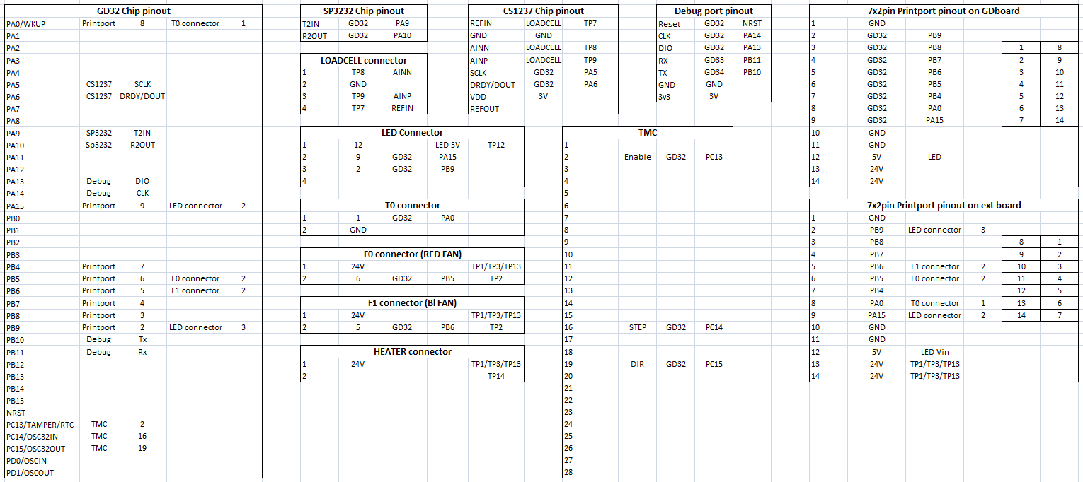
The project continues to focus on the GD32F303CBT6 microcontroller, around which the first complete hardware relationship database has now been established. Rather than being just a traditional pinout, the documentation has evolved into a continuously expanding hardware map linking MCU pins with peripherals, connectors, and test points across the entire toolhead PCB.
Progress so far
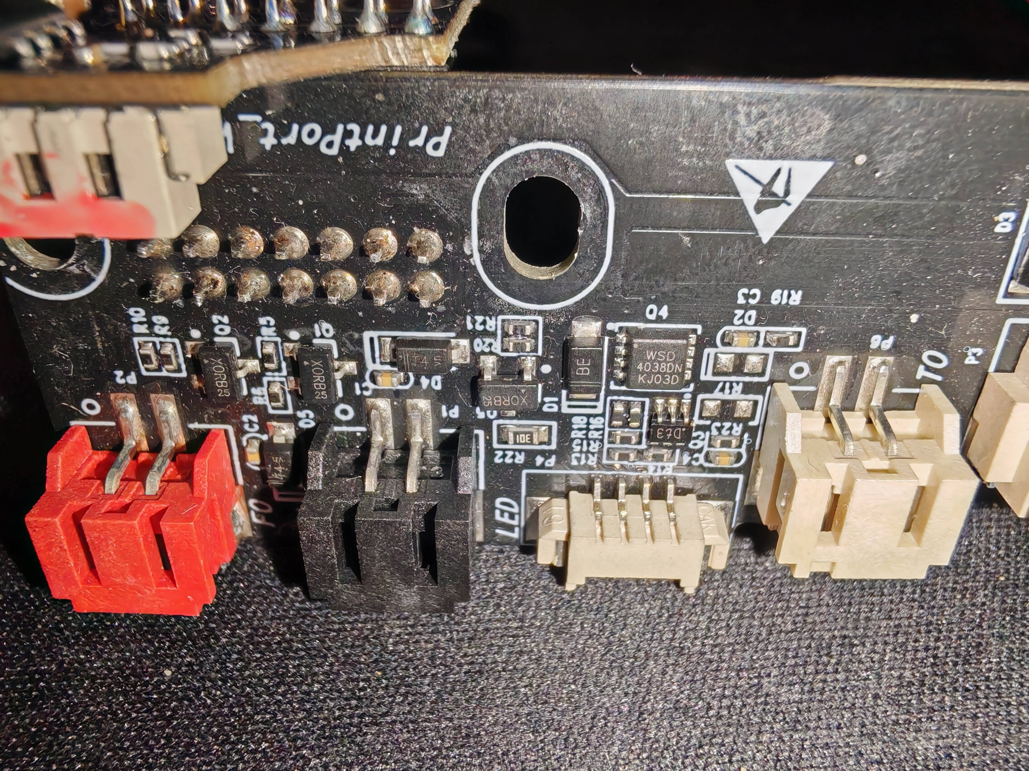
The TTL-side connections of the SP3232 RS232 transceiver have now been fully verified, along with the complete SWD debugging interface and the debug UART. This provides a reliable foundation for future firmware development and debugging.
Significant progress has also been made in documenting the CS1237 high-resolution ADC used for the toolhead load cell. Measurements have confirmed the communication lines between the GD32 MCU and the CS1237, while the load cell connector and its reference and measurement points have also been mapped.
The documentation of the 14-pin Print Port connecting the mainboard and the toolhead has been greatly expanded. In addition to the previously identified power rails, several signal lines have now been traced directly to the microcontroller, providing valuable insight into the internal communication architecture.
Work has also begun on documenting the TMC2209 stepper motor driver, fan control circuits, heater output, and LED control system.
A new documentation approach
From this point forward, the project is based on a structured hardware database. Every new measurement is recorded in a consistent format, including:
GD32 MCU pin assignments
Peripheral connections
Connector pinouts
Test points
Power distribution
Communication interfaces
This methodology ensures that the documentation remains expandable, verifiable, and easy for other developers to understand and contribute to.
What's next?
The next development phase will focus on identifying every remaining signal on the Print Port, completing the documentation of the TMC2209 driver, and fully mapping the fan, heater, and LED control circuitry.
The long-term objective remains unchanged: to completely document the original Anycubic Kobra 3 Toolhead electronics and develop an open, Klipper-compatible firmware that allows the factory PCB to operate as a fully independent toolboard.
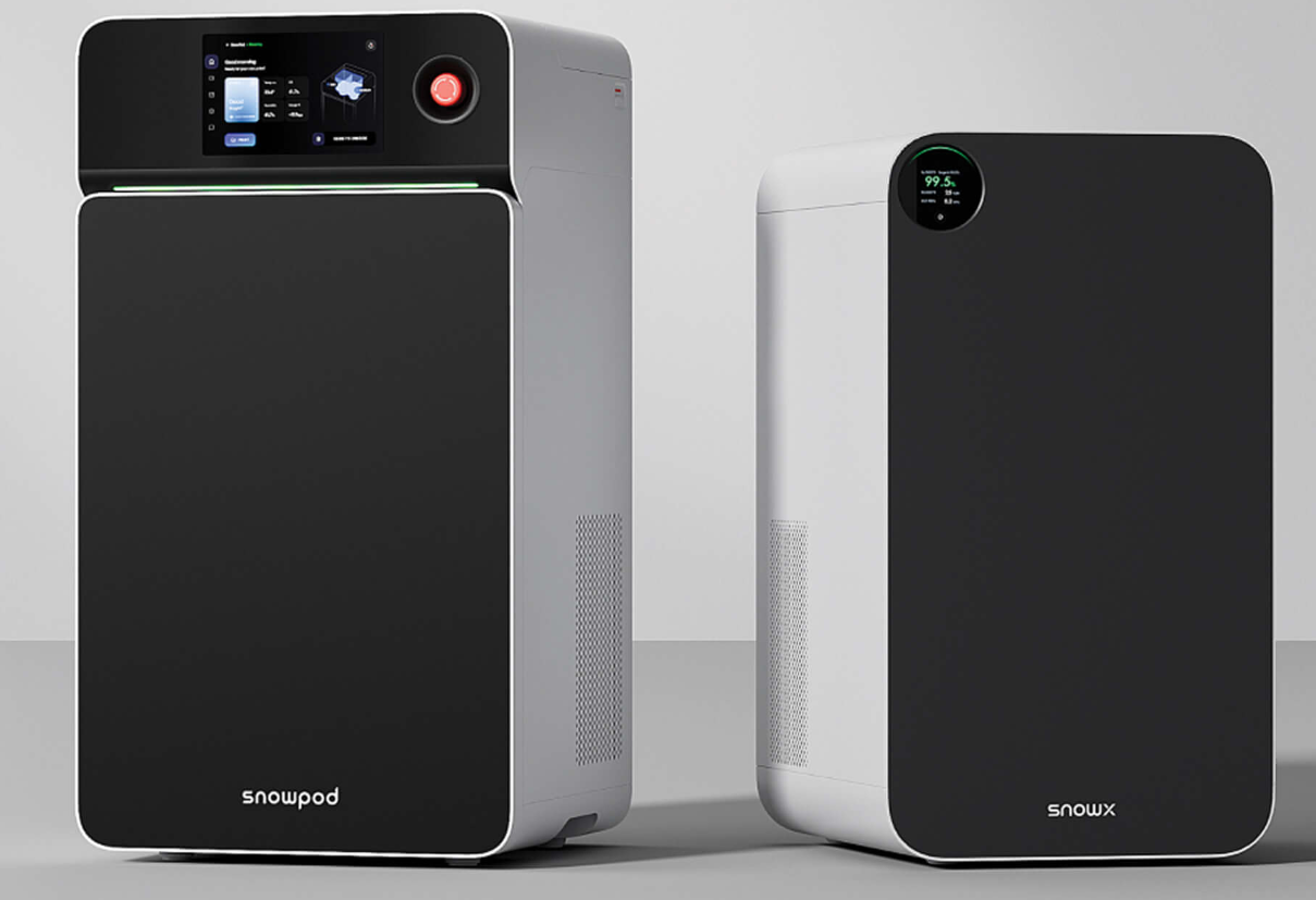
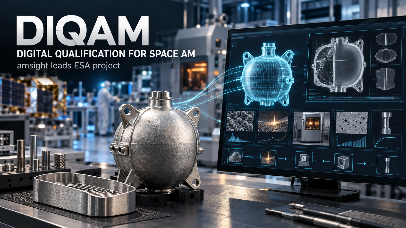
SnowX is developing SnowPod to bring laser powder bed fusion to smaller workspaces, emphasizing a 40 µm laser spot and more contained powder handling. Safety and ownership costs remain key questions.
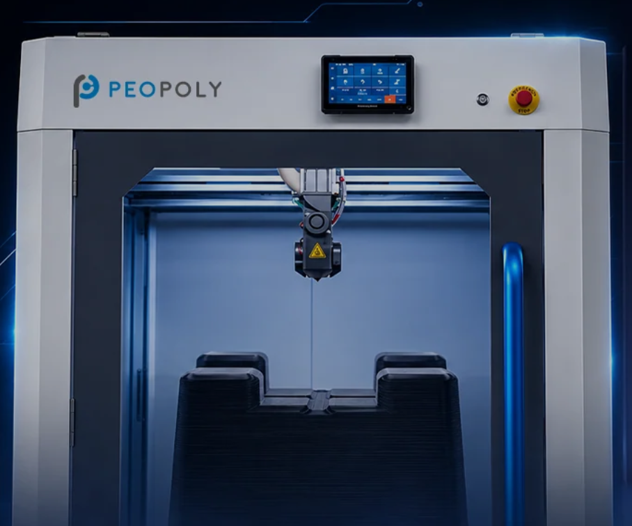
Peopoly opened general sales of its 800 mm-cube Giga 800 FGF printer on October 22, starting at $15,000 and adding laser-assisted leveling after early-adopter feedback.
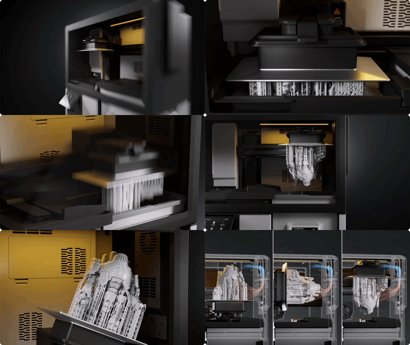
UniFormation’s S10 Kickstarter was active with October 22 updates. The 16K resin system integrates printing, washing and drying, but final UV curing is not automated.
Bambu Lab has confirmed the H3C and shown a nine-position tool rack. The full reveal is set for November 3, while price, specifications and availability remain undisclosed.
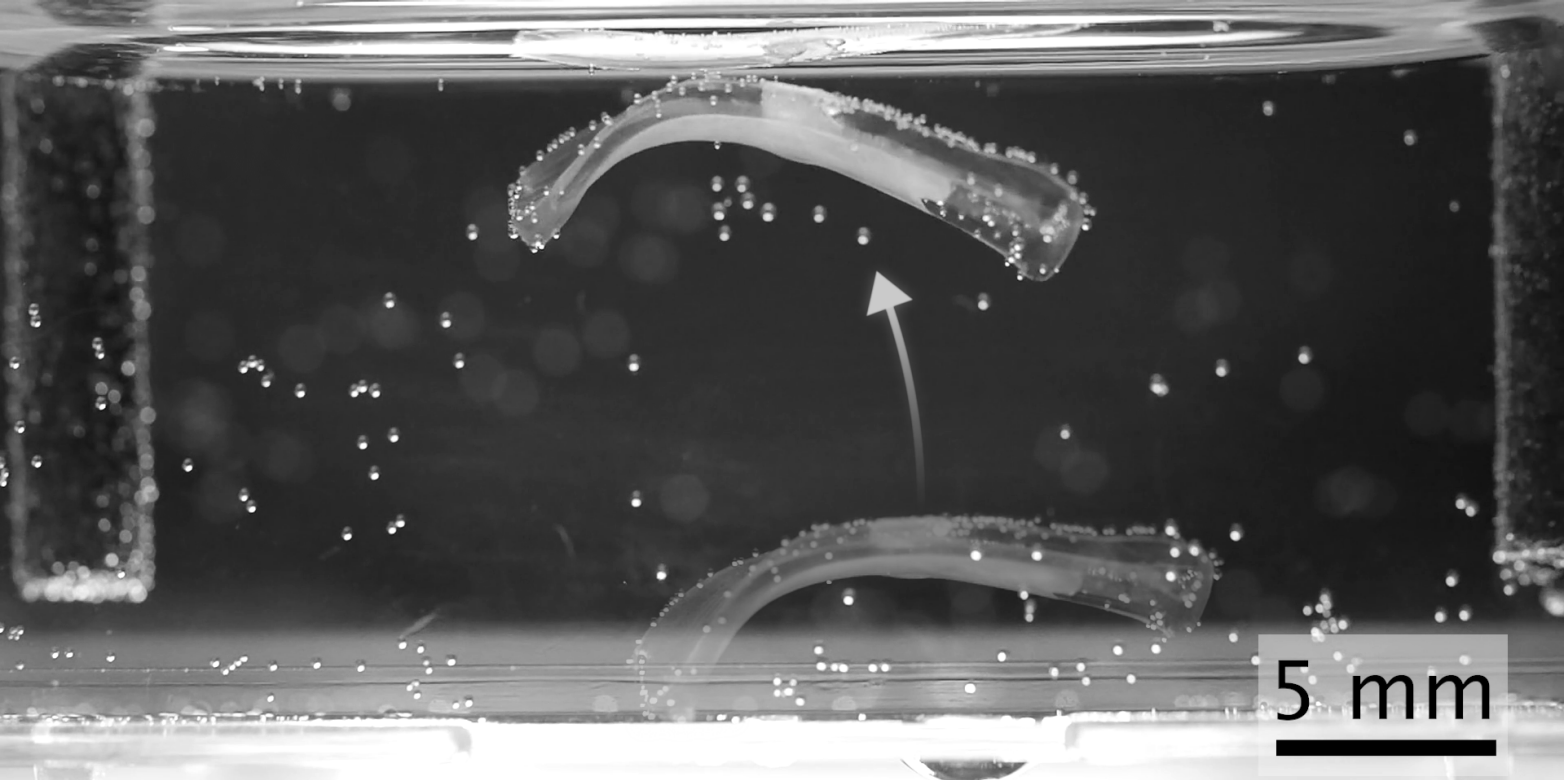
ETH Zurich researchers combined volumetrically printed hydrogel scaffolds with living muscle tissue to create biohybrid actuators, reporting up to elevenfold greater motion in selected comparisons.
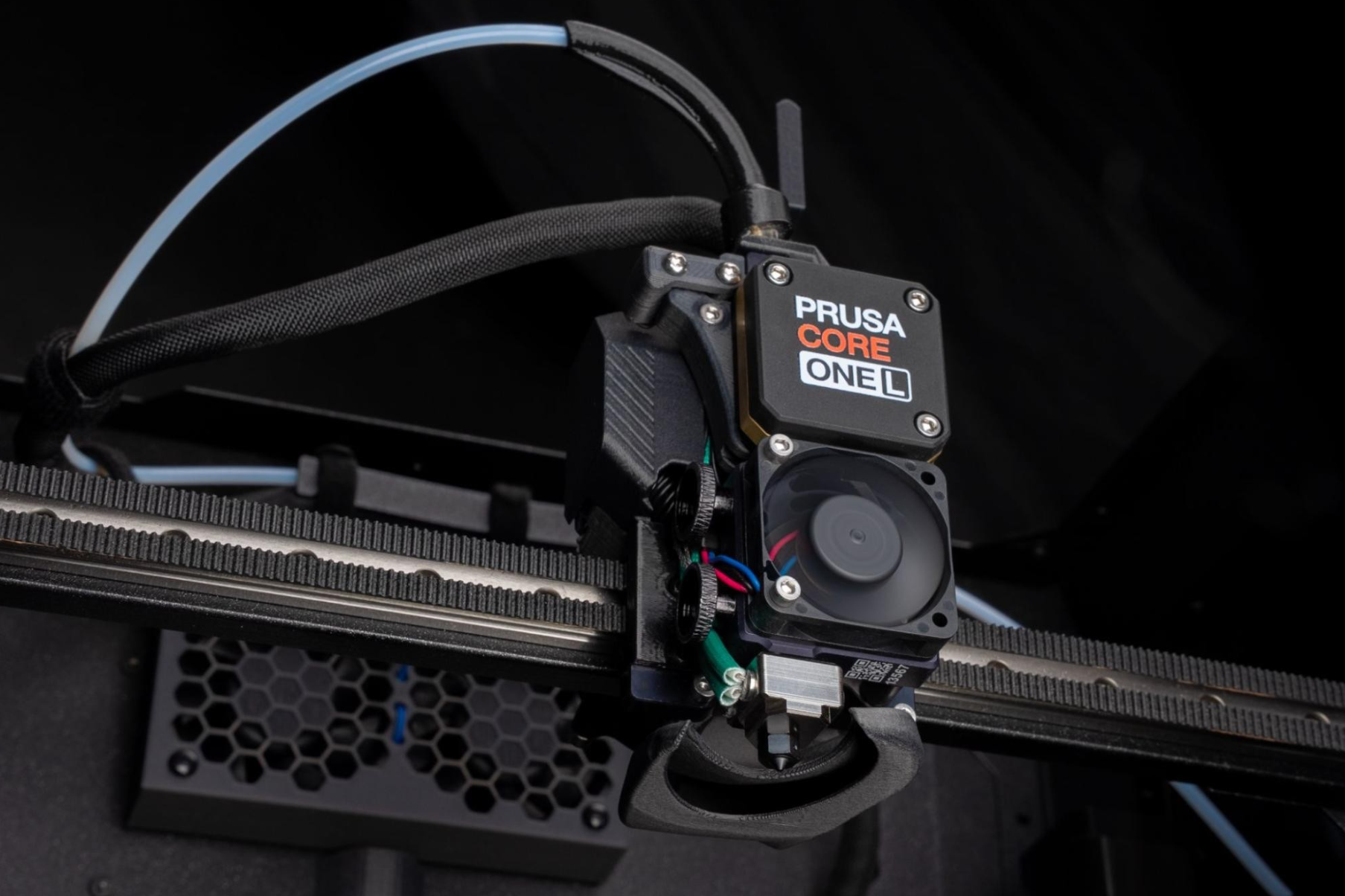
Prusa detailed its 400 °C HT Hotend, HighTemp build sheets and three engineering filaments on October 21. A hotter nozzle alone does not make a desktop printer a PEEK-capable industrial system.
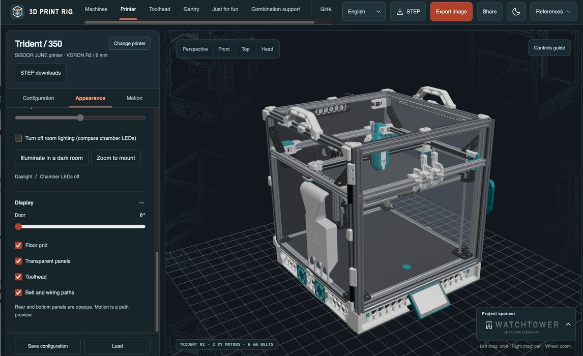
3D Print Rig brings PC-style component selection to DIY printers with a browser-based 3D preview. Users can compare toolheads and mechanical options, but physical compatibility still needs verification.
Elegoo has teased the M1 Ultra scanner, claiming 0.02 mm accuracy, wireless operation and touchscreen controls. Pricing and the underlying measurement technology are still undisclosed.
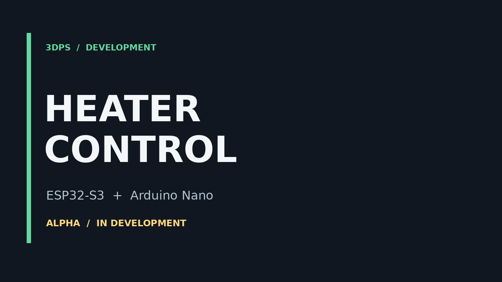
HEATER CONTROL began with two temperature sensors and a local display. Its development now includes a browser interface and a checked communication link, with configurable hardware assignment and a block-based rule editor forming the next steps.